Erection View Cleanup
- General Overview
- Tips and Tricks
- Related Tools
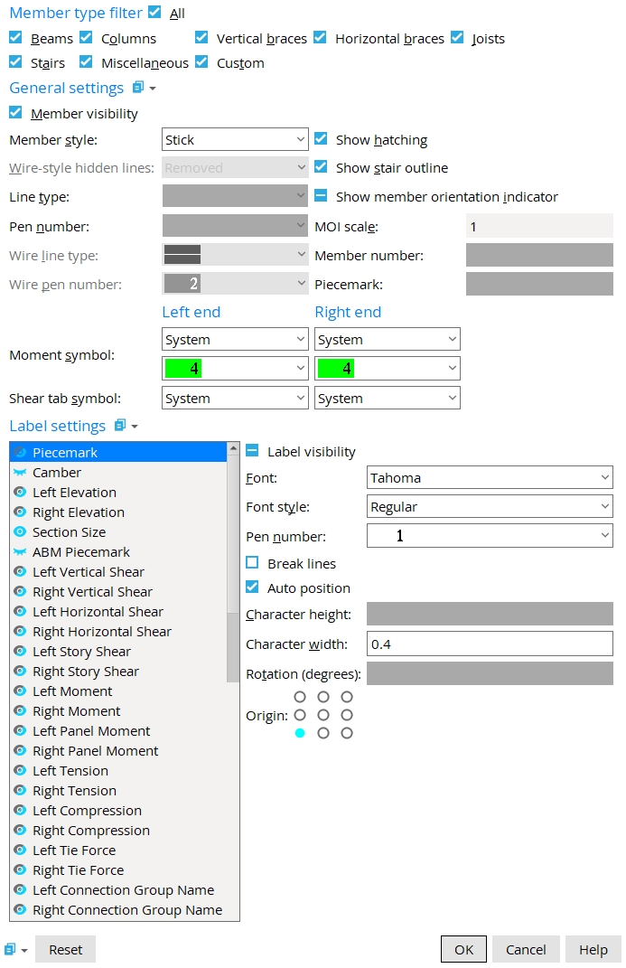
Member Type Filter
Member type filter: Select the member types to which the settings will apply. Settings will not be applied to any ![]() unchecked member type.
unchecked member type.
Note: Only the selected member types are shown when this window is open.
General Settings
|
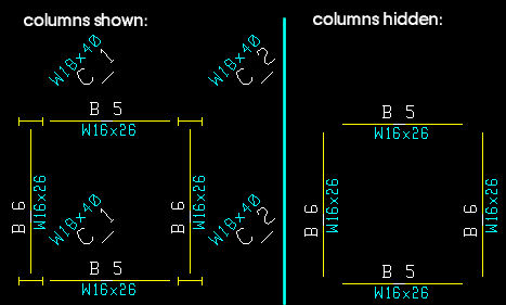
When this box
is checked, the member lines are displayed.
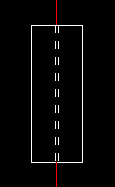
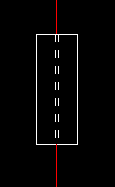
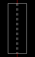
Member style: Stick or Wire or Solid. This determines the drawing style for the member(s).
|
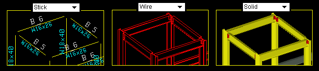
Stick draws a single line along the member’s workline and uses the Member orientation indicator selection to determine how the indicators are displayed.
Wire draws the materials that make up the member(s) with lines showing the geometrical shape.
Solid draws the materials that make up the member(s) to their true geometric shape and shades them according to their Surface finish.
Wire-style hidden lines: Removed or Dashed or Solid. When Member style is set to Wire, these options determine how hidden lines are drawn.
|
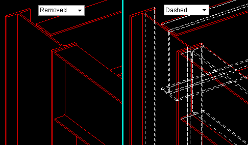
Removed hides lines that are covered by other steel in a view.
Dashed displays the lines that are covered by other steel as dashed lines.
Solid displays all lines as solid lines.
Line type: When Steel member style is set to Stick or Stick + wire, this option determines the line type of the member line.
Pen number: When Steel member style is set to Stick or Stick + wire, this option determines the pen color of the member line.
Tip: If you re-detail this 2D erection view, the choice you make here will be retained in the new drawing if you leave
Reset member line pens not checked.
Note: Assigning a pen number tells your printer how to draw an item. You can set line thickness for each drawing pen in Home > Project Settings > Fabricator > Detailing > Line Weights.
Wire line type: When Steel member style is set to Wire or Stick + wire, this option determines the pen color of the wire shape.
Tip: If you re-detail this erection view, the choice you make here will be retained in the new drawing if you leave
Wire pen number: When Steel member style is set to Wire or Stick + wire, this option determines the pen color of the wire shape lines.
Tip: If you re-detail this 2D erection view, the choice you make here will be retained in the new drawing if you leave
Note: Assigning a pen number tells your printer how to draw an item. You can set line thickness for each drawing pen in Home > Project Settings > Fabricator > Detailing > Line Weights.
When this box
|
When Steel member style is set to Stick and this box
Tip: Stair member lines and stair outlines are controlled independently. To show just the outlines of stringers, risers, and nosings for stairs you select, check
Detail Erection Views: If the option to
Show member orientation indicator: ![]() or
or ![]()
|
When this box
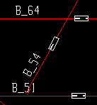
Tip: You can click and drag the MOI to relocate it.
MOI scale: 1 or a decimal fraction or a decimal multiple of 1.
|
When the MOI scale is 1, the MOI is drawn to the actual dimensions of the member's main material that are specified in the local shape file.
A decimal fraction (such as 0.5 or 0.25) shrinks the MOI to that fraction of its original size
A decimal multiple (such as 1.2 or 1.5) expands the MOI to that multiple of its original size.
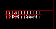
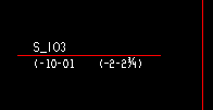
Member number: read-only. This shows the member number when a single member is edited.
Piecemark: read-only. This shows the member piecemark when a single member is edited.
Moment symbol: System or Hidden or Shown. This applies when the Steel member style is Stick or Stick + wire and the member is a beam.
|
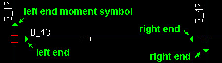
System displays a moment symbol on the end of the member if the member has a Bolted or Welded Moment type connection on that end.
Hidden hides the moment symbol on the end of the member.
Shown displays a moment symbol on the end of the member regardless of the connection in Modeling.
You can also select the display color for the symbol for members that have a symbol shown.
Tip: If you want the symbol closer to or farther from the end, you can drag it along the member line.
Shear tab symbol: System or Hidden or Near side or Far side. This applies when the Steel member style is Stick or Stick + wire and the member is a beam. A shear plate side indicator is associated with the supported beam's member line and is placed to show which side of the supported beam's web the shear plate attaches to.
|
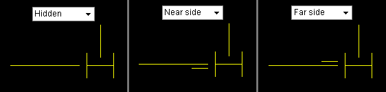
System displays a shear plate in stick form on the end of the beam if the member has a single-plate Shear connection.
Hidden hides the shear plate side indicator on that beam's end.
Near side displays a shear plate side indicator on the near side of the beam.
Far side displays a shear plate side indicator on the far side of the beam.
Label Settings
Label type: Select one or more label types to adjust their settings. Any custom property with ![]() Erection View Member Labels checked will appear in this list.
Erection View Member Labels checked will appear in this list.
Tip: To select multiple label types, either left-click and drag your mouse cursor over the desired labels, or hold the Ctrl key while clicking each label you want to edit.
|

When this box
Note: The icons (
or
) next to the label type indicate whether or not the label is visible.
Font: Any font that is listed can be selected.
Font style: The Bold, Bold Italic, Italic, or Regularstyle of the Font. Different fonts may have different styles available to them.
Also see: Home > Project Settings > Fabricator > Detailing > Drawing Presentaton > Fonts
Pen number: determines the pen color of the selected labels.
Also see: Home > Project Settings > Fabricator > Detailing > Line Weights
|
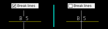
When this box
|
When this box
Note: This box
Also see: Relocate piecemarks and other member labels to default locations
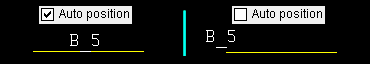
Character height: The height (in millimeters) of the label's text. This option is deactivated when Auto position ![]() is checked.
is checked.
|
Note: The default character height for piecemarks in erection views -- both 2D and 3D -- comes from the Drawing Presentation setup option Piecemark character height.
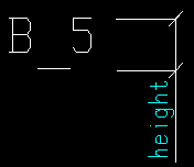
Character width: The width/height(in millimeters) of the label's text.
|
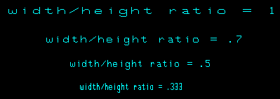
Note: The default width/height ratio for piecemarks in erection views -- both 2D and 3D -- comes from the Drawing Presentation setup option Piecemark width/height ratio.
Rotation: A positive or negative number of degrees, -360 to 360.
|
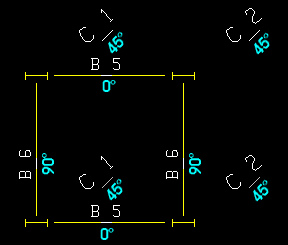
Tip: You can Ctrl and drag a label to rotate it around its origin. Ctrl + Shift and drag rotates the label at 45 degree increments.
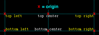
Origin: Top left or Top center or Top right or Bottom left or Bottom center or Bottom right. Labels are justified with respect to their origin point.
|

|
|
Reset undoes all changes made to this screen since you first opened it. The screen remains open.
OK (or the Enter key) closes this screen and applies the settings.
Cancel (or the Esc key) closes this screen without saving any changes.
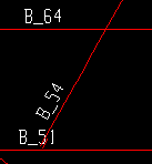
- You can select multiple members on a 2D erection view, then right-click and choose Edit on the context menu to clean up multiple members at the same time.
- Red or yellow exclamation point icons
 or
or 
- This window will open when multiple items are selected in the drawing, even if other non-member objects are also selected.

